Introduction
If you’ve ever wanted to know exactly how much current your circuit is pulling, how much power your solar panel is delivering, or how healthy your battery pack is in real time, the INA219 is one of the best low-cost ICs for the job. In this project, we’ll build a complete voltage/current/power monitor using the INA219, an Arduino (or ESP32), and a tiny bit of code — and along the way, understand exactly how the chip works under the hood, straight from the datasheet.
What is the INA219?
The INA219 is a digital current shunt and power monitor IC from Texas Instruments, communicating over I2C. Instead of using an analog ammeter or a separate ADC + amplifier circuit, the INA219 does everything internally:
- Measures the tiny voltage drop across a shunt resistor (to calculate current)
- Measures the bus voltage (the actual supply voltage on the high side)
- Internally multiplies current × voltage to give you power — no extra math needed (though you can also calculate it yourself)
- Reports everything over I2C as clean digital values
PCB Manufacturer
PCBWAY is a highly skilled company specializing in PCB manufacturing. They offer their services at incredibly low prices, such as providing 10 PCBs for only $5. Additionally, new members receive a $5 bonus. The website allows customers to upload their Gerber Files and place orders.

PCBWAY is known for producing PCBs of exceptional quality and maintaining high standards, which is why many people trust them for their PCB and PCBA needs.
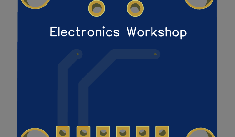
Below are some of my PCB’S manufactured by PCBWAY and I am fully satisfied by their Quality of service they provide
Key specifications
| Parameter | Value |
|---|---|
| Supply voltage (VS) | 3.0 V – 5.5 V |
| Bus voltage measurement range | 0 V – 26 V |
| Shunt voltage measurement range | ±320 mV (programmable: ±40/±80/±160/±320 mV) |
| ADC resolution | 12-bit |
| Interface | I2C / SMBus (up to 2.94 MHz in High-Speed mode) |
| I2C address range | 16 selectable addresses (via A0/A1 pins) |
| Current sense method | High-side shunt resistor |
| Package | SOT-23-8 / SOIC-8 |
The chip has four key internal registers you’ll interact with: Configuration, Shunt Voltage, Bus Voltage, Power, and Current (plus a Calibration register that ties it all together).
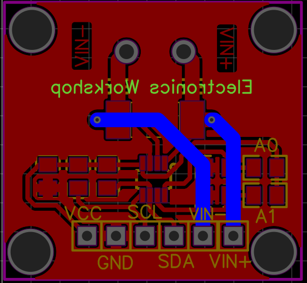
Circuit diagram
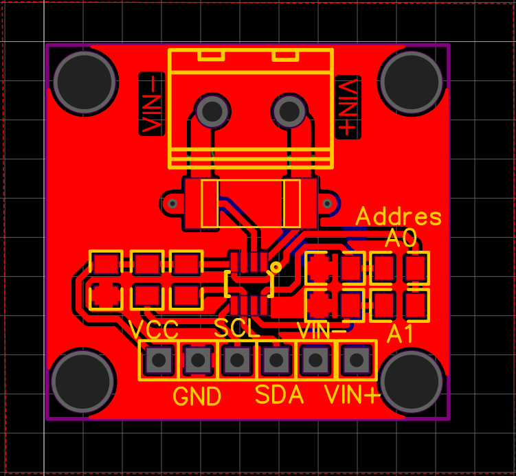
In this schematic, current to be measured flows from connector P1 through the 0.1 Ω shunt resistor (R5) and into the INA219’s IN+/IN- pins, which sense the tiny voltage drop across the shunt to calculate current — the VIN+/VIN- test points let you probe this directly. The chip is powered through VCC on pin 4 (VS), with the 100 nF capacitor (C1) decoupling supply noise right at the IC, and GND tied on pin 3.
The A0 and A1 address pins (5 and 6) are pulled to GND through 10 kΩ resistors (R1, R2), setting the I2C address to the default 0x40; they could alternatively be jumpered to VCC for a different address. SDA and SCL (pins 8 and 7) are pulled up to VCC through another pair of 10 kΩ resistors (R3, R4), as required for any I2C bus, then broken out to labeled connectors alongside VCC, VIN+/VIN-, and GND — giving you a clean set of header pins to wire this board into a microcontroller and the circuit you want to monitor.
How Current Sensing Actually Works
This is the part most tutorials skip, but it’s the heart of understanding the chip.
The shunt resistor principle
To measure current without breaking the circuit and inserting a meter, we place a very low-value resistor (the “shunt”) in series with the load — typically 0.1 Ω. As current flows through this resistor, it creates a small voltage drop, governed by Ohm’s Law:
V_shunt = I_load × R_shuntFor example, with a 0.1 Ω shunt and 1 A flowing through it, you get a 100 mV drop. The INA219’s internal differential amplifier measures this tiny drop with high precision (resolution as fine as 10 µV per bit at the lowest gain setting) and converts it into a digital value.
High-side vs low-side sensing
The INA219 uses high-side sensing — the shunt sits between the positive supply rail and the load (rather than between the load and ground). This has a big advantage: it lets you measure current and detect ground faults, since the ground path remains intact and continuous for the rest of the circuit.
Bus voltage
Separately, the chip measures the voltage on the load side of the shunt relative to ground — this is your bus voltage, i.e., the actual voltage the load is seeing (0–26 V range, 4 mV resolution).
Power calculation
Once the chip knows current and bus voltage, it calculates power internally:
P = V_bus × IThis happens inside the IC itself using a multiplier circuit — you don’t need your microcontroller to do this math, though it’s simple enough to do anyway if you prefer.
PCB Files
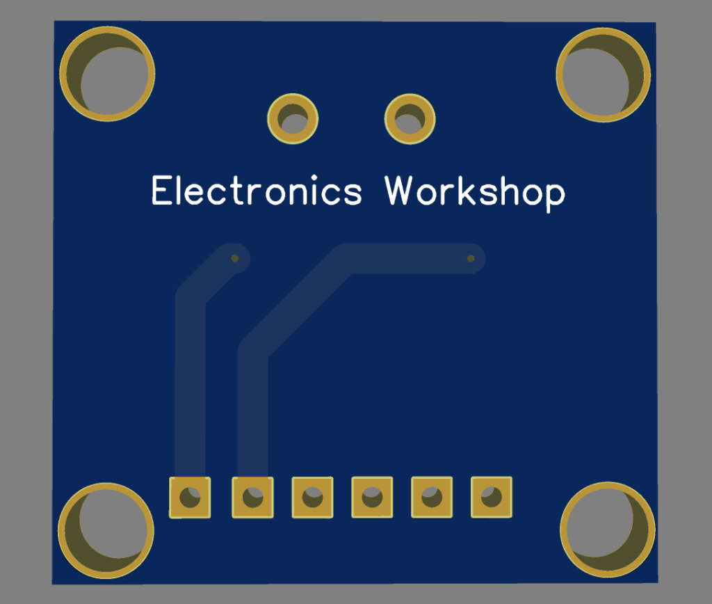
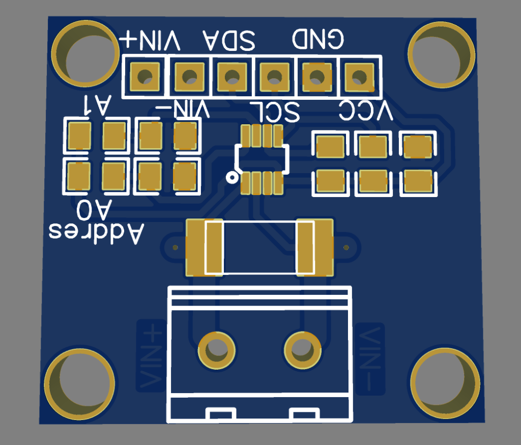
3D View
Manufacturing Files
Gerber
Bill Of Material
Pick and Place
Order Directly from PCB WAY
I have already uploaded all these required manufacturing files in PCBWAY website. You can easily go to the below link and place you order, and get your Own Home Automation PCB manufactured from one of the best pcb manufacturer PCBWAY
Real-World Applications
This exact build can be reused for:
- Battery monitoring — track discharge current and remaining capacity on a Li-ion pack
- Solar panel logging — measure instantaneous power output across the day
- Motor/actuator diagnostics — detect stalls via current spikes
- USB power meter — measure how much current a device actually draws
- EV / BMS prototyping — INA219-style high-side sensing is the same principle used (at higher voltage/current scale) in real battery management systems
Given your interest in electronics calculators and PCB projects, this also makes a great standalone PCB design exercise — a 2-layer board with the INA219, screw terminals for VIN+/VIN-, an I2C header, and silkscreened pinouts would be a clean, practical PCBWay-style project to document and showcase.
Conclusion
The INA219 turns what used to be a multi-component analog measurement circuit (op-amp + shunt + ADC + math) into a single, accurate, I2C-addressable chip. With under $5 in parts and 20 lines of code, you get real-time voltage, current, and power readings — accurate enough for serious projects like solar logging, battery monitoring, or power-budgeting an embedded system.
From here, natural next steps are logging the data to an SD card, streaming it to a web dashboard over WiFi (ESP32), or even feeding it into a closed-loop control system that throttles a load based on real-time power draw.
FAQ Section
Q: What is the INA219 used for? A: It’s an I2C current/power monitor IC used to measure voltage, current, and power in a circuit without breaking it apart for analog metering.
Q: What is the default I2C address of the INA219? A: 0x40, when address pins A0 and A1 are both tied to GND.
Q: What shunt resistor value does the INA219 use? A: Most breakout boards use a 0.1 Ω shunt resistor, giving a measurement range up to ±3.2A at default gain settings.
Q: Can the INA219 measure negative current? A: Yes — it’s bidirectional. Reversed current flow (VIN+ and VIN- swapped) shows as a negative value.
Q: INA219 vs INA226 — which is better? A: The INA226 offers higher resolution and an internal alert function, while the INA219 is cheaper and sufficient for most hobbyist projects