
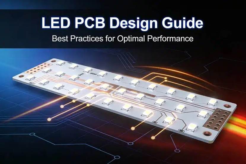
LED PCB Design Guide
LEDs (light-emitting diodes) are everywhere—from home LED strips and ceiling lights to outdoor advertising screens and car taillights—and behind every reliable LED device is a well-designed LED PCB. Unlike regular consumer electronics PCBs, the core requirements for an LED PCB focus on heat dissipation, current uniformity, and reliability. Many beginner-designed LED PCBs suffer from uneven brightness, excessive heat, short lifespan, or even mass failures, which usually stem from overlooked design details.
This LED PCB design guide is tailored for beginners and entry-level engineers. It avoids complex electromagnetic simulations and advanced theory, focusing instead on practical, implementable, and problem-avoiding strategies. From requirements analysis, material selection, layout and routing, to thermal design, process specifications, and troubleshooting, this guide breaks down the essential points of LED PCB design, helping you quickly master core skills and create stable, reliable, and functional LED PCBs.
Whether you’re designing a small home LED panel or a compact LED module, this guide provides practical advice to avoid common beginner mistakes.
Preparation Before Design
The first step in LED PCB design is not to start drawing, but to clarify the requirements. Different applications demand different design priorities. A common mistake for beginners is blindly copying others’ designs, ignoring their own requirements, which usually leads to design failures. Before starting, make sure to define the following three core requirements:
Define LED Specifications and Quantity
This forms the foundation of your design, directly determining PCB size, current, and routing strategy:
- Single LED parameters: Identify the rated voltage (e.g., 3.2V, 5V), rated current (e.g., 20mA, 300mA), and package type (e.g., 3528, 5050, COB, high-power equivalent-lumen).
- LED quantity and connection type: Determine the total number of LEDs and how they will be connected (series, parallel, or a combination). Series LEDs require attention to total voltage; parallel LEDs require attention to total current; combined connections need careful current balancing across branches.
Example: Ten 3.2V, 20mA LEDs in series have a total voltage of 32V (3.2V × 10) and total current of 20mA. In parallel, the total voltage is 3.2V, and the total current is 200mA (20mA × 10).
Determine Operating Environment and Thermal Requirements
LEDs convert roughly 30%-50% of input energy into light, with the remainder becoming heat. Higher temperatures reduce brightness and shorten lifespan (roughly, every 10℃ increase halves the lifespan). Therefore, heat dissipation requirements must be determined based on the environment:
- Indoor scenarios (ceiling lights, LED strips): Lower ambient temperature, minimal thermal pressure, standard PCB is usually sufficient.
- Outdoor scenarios (advertising screens, street lights): Higher ambient temperature and direct sunlight, significant thermal load, aluminum-based PCBs (MCPCBs) are recommended, with optional heat sinks.
- High-power LEDs (≥1W per LED): Always use aluminum-based PCBs and design thermal structures, such as thermal pads or vias.
Clarify Driving Method and PCB Size
LEDs require a driver to operate, and the driving method directly affects PCB design:
- Constant current driver (recommended): Provides stable current to prevent LED burnout. PCB must allocate space for the driver chip.
- Constant voltage driver: Suitable for simple parallel circuits (small indicator LEDs). Must match with appropriate current-limiting resistors.
- PCB size: Determine length and width according to installation space, leaving space for mounting holes and connectors to avoid fit issues.
Key Materials and Components Selection
When it comes to LED PCB design, material selection and core components are critical. Choosing the right materials significantly reduces thermal stress and failure rates, while selecting the right components ensures circuit stability and long lifespan. Beginners don’t need to pursue the most high-end options—choose cost-effective solutions that meet the requirements.
PCB Material Selection
LED PCB materials are mainly divided into three types. Beginners can select based on thermal requirements:
Standard FR-4 PCB:
- High cost-performance ratio and good insulation.
- Suitable for low-power LEDs (≤0.5W per LED) in indoor scenarios (e.g., indicators, small LED strips).
- Thermal performance is moderate; not suitable for high-power or high-temperature applications.
Aluminum-based PCB (MCPCB):
- Key advantage: high thermal conductivity (10–20× FR-4).
- Suitable for high-power LEDs (≥1W per LED), outdoor scenarios, and high-temperature environments (e.g., street lights, automotive LEDs).
- Two types: ordinary aluminum (thermal conductivity 1–2 W/(m·K)) and high-thermal aluminum (≥5 W/(m·K)).
- Beginners usually can meet most needs with standard aluminum-based PCBs.
Copper-based PCB:
- Highest thermal performance (≥200 W/(m·K)).
- Suitable for ultra-high-power LEDs (≥10W per LED) and industrial-grade LED applications.
- High cost; generally unnecessary for beginners.
Beginner Pitfall: Believing all LED PCBs must use aluminum. For low-power, indoor applications, FR-4 is sufficient. Using aluminum unnecessarily increases cost.
Core Component Selection
The main components of an LED PCB are SMD LEDs, driver chips, current-limiting resistors, and solder pads. Focus on the following:
LED Selection:
- Prefer LEDs from reputable manufacturers to ensure consistent parameters (voltage, current, brightness).
- Avoid mixing LEDs with different specs, which can cause uneven brightness or burnout.
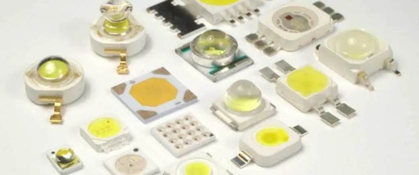
- Package choice:
3528, 5050 for LED strips and ceiling lights
COB for panel lights and surface lighting
High-power equivalent-lumen LEDs for street lights or spotlights
Driver Chip Selection:
- Prefer constant current drivers (e.g., TP4056, LM3406).
- Output current should exceed the total LED current by at least 10% (driver output ≥ LED total current × 1.1).
- For constant voltage drivers, pair with appropriate current-limiting resistors:
Resistor value = (Power Supply Voltage – LED Rated Voltage) / LED Current
Current-Limiting Resistor Selection:
- Protects LEDs from excessive current.
- Power rating ≥ (Current² × Resistance) × 2 (to leave safety margin).
- Prevents resistor overheating and burnout.
Solder Pad Selection:
- Match pad size to LED package:
3528 LED pad: ~3.5mm × 2.8mm
5050 LED pad: ~5mm × 5mm
- Pads too large → risk of solder bridging
- Pads too small → poor contact
6 Must-Follow Layout and Routing Principles for Beginners
The layout and routing of an LED PCB are crucial, directly affecting brightness uniformity, thermal performance, and circuit stability. Beginners don’t need complex routing tricks—simply follow these six principles to avoid common issues and ensure a functional design.
Principle 1: LED Layout—Uniformity First, with Thermal Consideration
- Even Distribution: Arrange LEDs evenly within the same module (e.g., matrix or linear patterns) to prevent local hot spots and uneven brightness.
- Proper Spacing: Adjust spacing according to application:
LED strips: 10–20 mm between LEDs
Ceiling lights: 20–30 mm
Outdoor LED displays: spacing based on pixel density requirements
- Thermal Layout:
Keep high-power LEDs away from heat-generating components like driver chips or resistors.
On aluminum PCBs, place LEDs close to the aluminum layer to improve heat dissipation.
Principle 2: Separate Driver Circuit from LED Circuit
Driver chips and resistors generate heat and electromagnetic interference. Placing them too close to LEDs can affect brightness stability and lifespan.
- Placement: Position driver circuitry on one end of the PCB, LED circuit on the other, leaving 5–10 mm separation.
- Thermal Consideration: Ensure driver chips have heat-dissipating pads close to aluminum layers (for MCPCBs) or reserve heat-dissipation space to prevent overheating.
Principle 3: Routing—Ensure Uniform Current and Adequate Trace Width
LEDs are sensitive to current stability. Routing should prioritize current uniformity and sufficient trace width.
- Series Circuits: Keep traces as straight as possible to ensure consistent current across LEDs.
- Parallel Circuits: Match branch trace length and width to prevent uneven current distribution.
- Trace Width Guidelines:
Standard LED branch (≤100 mA): ≥0.2 mm
High-power LED branch (≥300 mA): ≥0.5 mm
Power traces (≥1A total): ≥1.0 mm
Principle 4: Ground Design—Simple, Reliable, and Interference-Free
Grounding should be reliable, not complicated. Proper grounding reduces electromagnetic interference and ensures stable operation.
- Single-Point Ground: Connect all grounds (driver chip, LED, power supply) to a single point to avoid potential differences.
- Ground Trace Width: ≥0.3 mm, preferably straight, to ensure good conductivity.
- MCPCB Grounding: Connect driver chip ground directly to the aluminum layer to enhance both heat dissipation and EMI resistance.
Principle 5: Reserve Thermal Structures to Extend LED Lifespan
Even without aluminum PCBs, reserve thermal structures for high-power LEDs.
- Heat-Dissipating Pads: Design large pads beneath LEDs and driver chips (≥2× LED package area).
- Thermal Vias: Place evenly across the heat pad (0.3–0.5 mm diameter, 1–2 mm spacing) to conduct heat to the PCB back or aluminum base.
- Space for Heat Sinks: Reserve room for potential heatsink installation on PCB back for high-power applications.
Principle 6: Reserve Mounting Holes and Test Points for Production and Debugging
Beginners often overlook mounting holes and test points, complicating production and testing.
- Mounting Holes: Reserve 2–4 holes (2–3 mm diameter), ≥5 mm from PCB edge to prevent edge cracking.
- Test Points: Include points on LED branches, power lines, and driver chip outputs (≥1 mm pads) for measuring voltage/current and troubleshooting.
Align with Manufacturing to Ensure Design Feasibility
Many beginner LED PCB designs are logically correct but cannot be manufactured or fail frequently after production. The core reason is ignoring manufacturing process standards. When designing, follow these four key guidelines to align with SMT (Surface Mount Technology) production.
Pad Design—Compatible with SMT Assembly
- Pad Size: Design strictly according to the LED package datasheet to avoid oversized pads (causing solder bridges) or undersized pads (causing cold joints).
- Pad Spacing: Maintain at least 0.2 mm between adjacent pads to prevent bridging during assembly.
- Pad Edge Clearance: Ensure pad edges are ≥0.5 mm from PCB edge to prevent edge damage during placement.
Solder Mask and Silkscreen—Clear and Standardized
- Solder Mask: Leave openings on LED pads for soldering; cover other areas to protect traces and prevent short circuits.
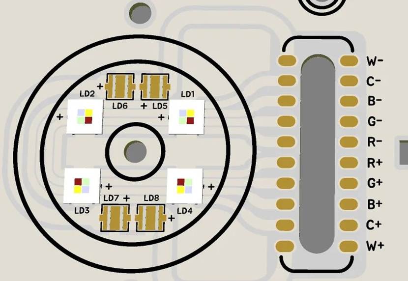
- Silkscreen: Clearly mark LED polarity (“+” and “–”), driver chip pins, and test point functions to simplify assembly and debugging.
Avoid Sharp Angles and Fine Traces
- Trace Angles: Avoid sharp angles (≤90°); use rounded corners (≥135°) to prevent trace breaks and signal interference.
- Trace Width: Avoid very fine traces (<0.15 mm) as they are prone to breakage, heating, and difficult manufacturing. Beginners should stick to ≥0.2 mm for standard traces.
Confirm Manufacturing Capabilities with Your PCB Vendor
Before production, send your PCB files to the manufacturer to verify feasibility:
- Aluminum PCB thickness, thermal via diameters
- Minimum trace width and spacing
- SMT assembly compatibility
This prevents designs that cannot be fabricated due to manufacturer limitations.
Conclusion
For beginners, LED PCB design doesn’t have to be complicated. The three core principles to keep in mind are: stability (consistent current and reliable circuitry), uniformity (even LED placement for consistent brightness), and heat management (effective cooling to extend LED lifespan).
After completing your design, it’s highly recommended to consult with a professional LED PCB solution provider. Even if you have followed all design guidelines, experienced engineers can review your layout, suggest improvements, optimize thermal performance, and help avoid potential production issues. Working with a professional partner ensures your LED PCB is not only well-designed but also ready for reliable, real-world manufacturing.
By combining careful design with expert review, you can confidently produce stable, efficient, and high-quality LED PCBs, whether it’s for small indoor projects or larger, high-power modules.