Introduction
Modern electronic systems require stable and efficient power supplies to ensure reliable operation. Whether you’re powering embedded systems, robotics, IoT devices, or industrial electronics, converting a higher DC voltage into a regulated lower voltage is one of the most common design challenges.
The SY8205 synchronous buck converter is an excellent solution for high-current, high-efficiency voltage conversion. It offers excellent efficiency, compact PCB design, and minimal external components, making it ideal for battery-powered and embedded applications.
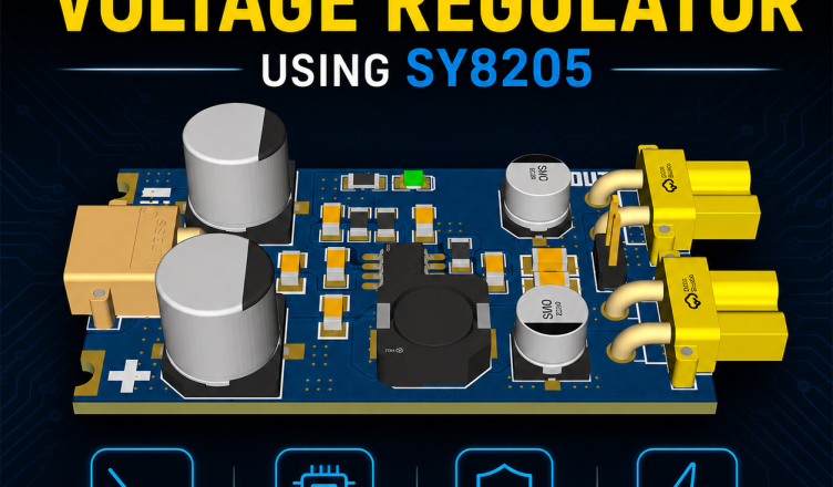
In this article, we’ll explore the design, working principle, PCB implementation, and applications of a DC-DC Step-Down Voltage Regulator Using SY8205.
PCB Manufacturer
PCBWAY is a highly skilled company specializing in PCB manufacturing. They offer their services at incredibly low prices, such as providing 10 PCBs for only $5. Additionally, new members receive a $5 bonus. The website allows customers to upload their Gerber Files and place orders.

PCBWAY is known for producing PCBs of exceptional quality and maintaining high standards, which is why many people trust them for their PCB and PCBA needs.
Below are some of my PCB’S manufactured by PCBWAY and I am fully satisfied by their Quality of service they provide.
What is a DC-DC Step-Down Converter?
A DC-DC step-down converter, also known as a Buck Converter, converts a higher DC input voltage into a lower regulated output voltage while maintaining high efficiency.
Unlike traditional linear regulators, switching regulators waste very little power as heat.
For example:
| Input Voltage | Output Voltage |
|---|---|
| 12V | 5V |
| 24V | 5V |
| 15V | 3.3V |
| 9V | 5V |
Efficiencies typically range from 90% to 95%, making buck converters the preferred choice for modern electronic designs.
Why Choose the SY8205?
The SY8205 is a high-performance synchronous buck converter designed for compact and efficient power supply applications.
Key Features
- Wide input voltage range
- High output current capability
- Integrated MOSFETs
- High conversion efficiency
- Fixed switching frequency
- Short-circuit protection
- Thermal shutdown protection
- Over-current protection
- Soft-start functionality
- Compact SOP package
These features simplify PCB design while reducing component count and improving reliability.
Typical Specifications
| Parameter | Value |
|---|---|
| Input Voltage | 7V – 24V (Typical) |
| Output Voltage | 5V (Configurable) |
| Maximum Output Current | Up to 5A |
| Efficiency | Up to 95% |
| Switching Frequency | High-frequency PWM |
| Converter Type | Synchronous Buck Converter |
How the SY8205 Works
The SY8205 operates using Pulse Width Modulation (PWM) to regulate the output voltage.
Its operation consists of four main stages:
1. Input Filtering
The input capacitor filters supply noise and provides stable power to the regulator.
2. Switching Stage
The internal MOSFET switches rapidly at high frequency, transferring energy to the inductor.
3. Energy Storage
The inductor stores energy while the switch is ON and releases it when the switch turns OFF.
4. Output Filtering
The output capacitor smooths the switching waveform into a clean, stable DC voltage.
This switching mechanism minimizes power loss and maximizes efficiency.
Circuit Diagram
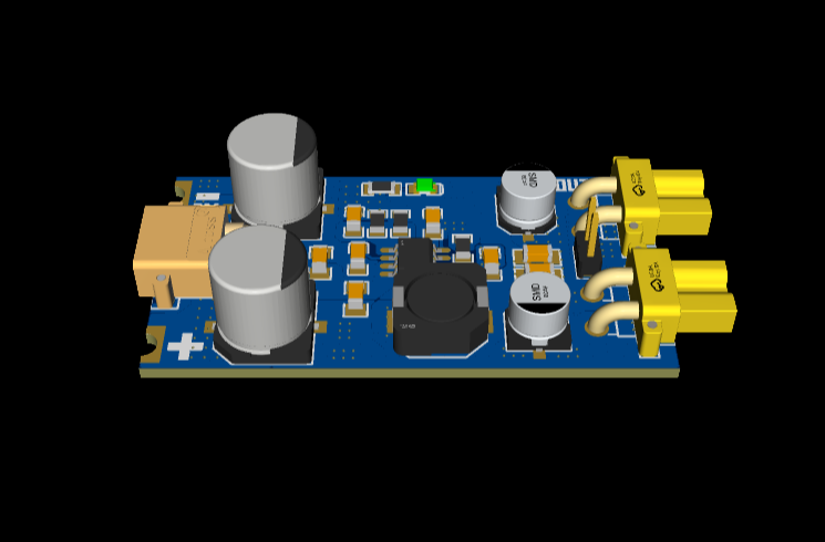
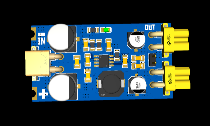
The circuit shown is a DC-DC step-down (buck) voltage regulator based on the SY8205FCC synchronous buck converter IC, designed to convert a higher DC input voltage into a stable lower output voltage with high efficiency. The input power is supplied through the XT30PW-M connector (CN1) and is filtered by a combination of bulk electrolytic capacitors (C7, C8, U2, and U3) and ceramic capacitors (C6) to reduce voltage ripple and suppress high-frequency noise before reaching the regulator IC. The SY8205FCC (U1) serves as the main switching controller, while the bootstrap capacitor C1 supports the internal high-side MOSFET operation. The switching output from the LX pin passes through the 6.8 µH inductor (L1), which stores and releases energy during each switching cycle, producing a smooth DC output. The output voltage is further filtered using capacitors C4, C5, C9, and C10, ensuring a clean and stable supply for the connected load.
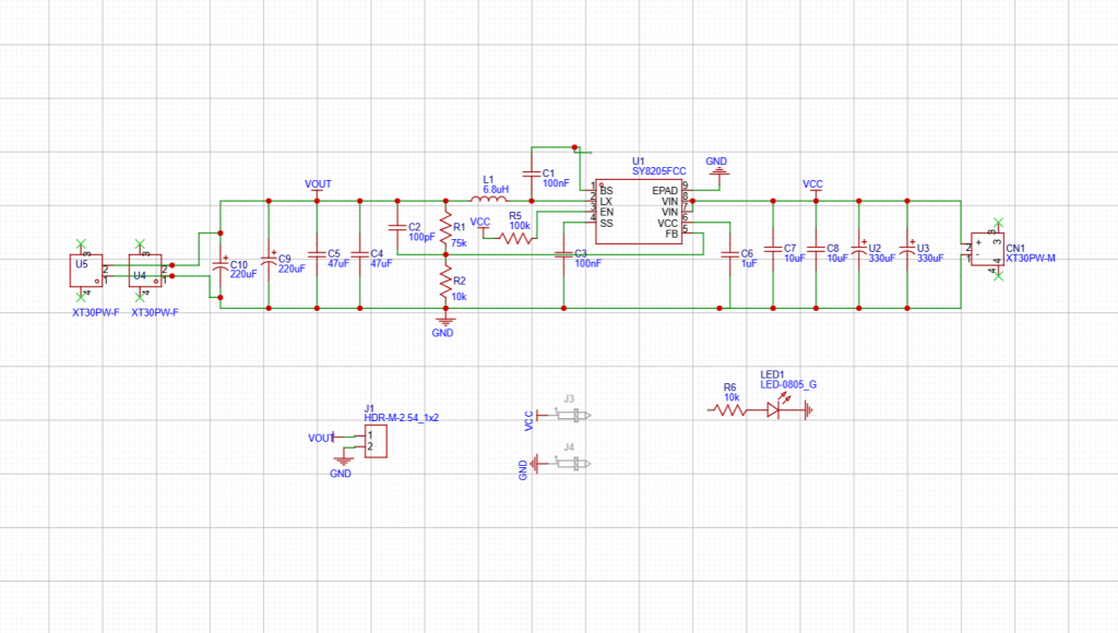
The output voltage regulation is achieved through the feedback network consisting of R1 (75 kΩ) and R2 (10 kΩ), which forms a voltage divider connected to the FB (Feedback) pin of the SY8205. This network continuously monitors the output voltage and allows the IC to adjust the switching duty cycle to maintain a constant regulated output despite variations in input voltage or load current. The R5-C3 network provides compensation and stability for the control loop, while C2 acts as a feed-forward capacitor to improve transient response and reduce output ripple. An XT30PW-F connector (U4/U5) and a 2-pin header (J1) provide convenient output connections, while LED1 with resistor R6 serves as a power indicator, illuminating whenever the regulator is energized. Overall, this circuit provides an efficient, compact, and reliable power supply suitable for applications such as embedded systems, robotics, IoT devices, communication equipment, and other electronics requiring a stable low-voltage DC source.
PCB files
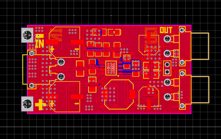
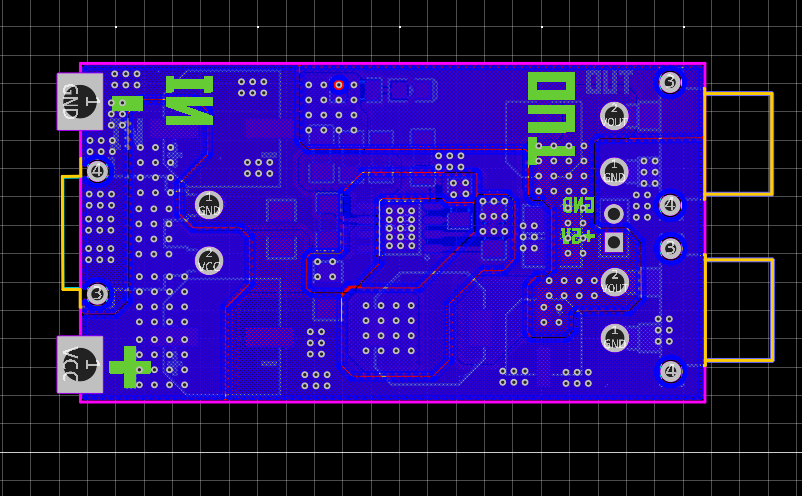
3D
Manufacturing Files
Gerber
Bill Of materials
Pick and Place
Order Directly from PCB WAY
I have already uploaded all these required manufacturing files in PCBWAY website. You can easily go to the below link and place you order, and get your Own Home Automation PCB manufactured from one of the best pcb manufacturer PCBWAY
Protection Features
The SY8205 incorporates several built-in protection mechanisms:
- Thermal Shutdown
- Overcurrent Protection
- Short-Circuit Protection
- Soft Start
- Under-Voltage Protection
These features improve long-term reliability and safeguard connected circuits.
Frequently Asked Questions (FAQ)
What is the SY8205?
The SY8205 is a synchronous buck (step-down) DC-DC converter IC designed for efficient voltage regulation in compact electronic systems.
What input voltage can the SY8205 accept?
Typical designs support input voltages from 7V to 24V, depending on the implementation and component selection.
What is the maximum output current?
Many SY8205-based designs can provide up to 5A with proper PCB layout and thermal management.
What is the efficiency of the SY8205?
Typical efficiency ranges from 90% to 95%, depending on input voltage, output voltage, and load current.
What are common applications?
The SY8205 is commonly used in embedded systems, robotics, IoT devices, industrial controllers, automotive electronics, and battery-powered equipment.
Conclusion
The DC-DC Step-Down Voltage Regulator Using SY8205 is a compact, efficient, and reliable solution for converting higher DC voltages into stable lower-voltage outputs. With high efficiency, integrated protection features, and support for high output currents, the SY8205 is an excellent choice for embedded systems, industrial electronics, robotics, and IoT applications.
By following good PCB layout practices and selecting quality passive components, designers can achieve excellent electrical performance, reduced heat generation, and long-term reliability in their power supply designs.
Numerical Calculator
Best free online calculators for engineers, students and everyday life — from Ohm’s Law, LED resistors and RLC resonance to BMI, calories, pregnancy due dates and EV savings — each with live diagrams and step-by-step math.
Numerical calculator : https://numericalcalculator.com/