
Introduction
Magnetic sensors are widely used in modern electronic systems for detecting the presence of magnets without requiring physical contact. In this project, we will design a magnetic sensor using the S411A Hall Effect sensor, a compact and reliable device that converts changes in a magnetic field into a digital output signal. The circuit is simple, requires only a few components, and is an excellent project for beginners, students, and electronics enthusiasts who want to learn about magnetic field sensing and PCB design.
Whether you’re building a proximity detector, door sensor, position detector, or automation project, the S411A Hall Effect sensor offers a reliable and low-cost solution.
PCB Manufacturer
PCBWAY is a highly skilled company specializing in PCB manufacturing. They offer their services at incredibly low prices, such as providing 10 PCBs for only $5. Additionally, new members receive a $5 bonus. The website allows customers to upload their Gerber Files and place orders.

PCBWAY is known for producing PCBs of exceptional quality and maintaining high standards, which is why many people trust them for their PCB and PCBA needs.
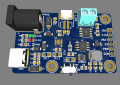
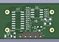
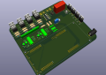
Below are some of my PCB’S manufactured by PCBWAY and I am fully satisfied by their Quality of service they provide.
What is a Hall Effect Sensor?
A Hall Effect sensor is a semiconductor device that detects magnetic fields by measuring the Hall voltage generated when a magnetic field passes through the sensor. Unlike mechanical switches, Hall Effect sensors have no moving parts, making them more durable, reliable, and suitable for high-speed switching applications.
Hall Effect sensors are commonly used in:
- Door and window security systems
- Speed detection
- Position sensing
- Motor control
- Robotics
- Automotive electronics
- Industrial automation
- Consumer electronics
Why Choose the S411A Hall Effect Sensor?
The S411A is a digital Hall Effect sensor designed for accurate magnetic field detection. It provides a clean digital output when a magnetic field of sufficient strength is present, making it ideal for switching and sensing applications.
Advantages of the S411A
- Compact TO-92 package
- Digital output
- High sensitivity
- Low power consumption
- Fast response time
- Reliable operation
- Wide operating voltage range
- Easy to interface with LEDs and microcontrollers
Pin Out of S411A
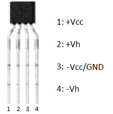
The S411A Hall Effect sensor is available in a compact 4-pin SIP (Single Inline Package), with each pin serving a specific function for magnetic field detection. Pin 1 (+VCC) is the positive power supply input, which powers the sensor using the recommended operating voltage. Pin 2 (+Vh) is the positive Hall voltage terminal, providing access to the internal Hall element for signal processing in certain applications. Pin 3 (−VCC/GND) serves as the ground or negative power supply connection, completing the power circuit. Pin 4 (−Vh) is the negative Hall voltage terminal, which works together with Pin 2 to generate the Hall voltage when a magnetic field is present. As a magnetic field passes through the sensor, a small Hall voltage is produced between the +Vh and −Vh terminals, and this signal can then be amplified or processed by external circuitry to detect the presence and strength of the magnetic field. This pin configuration makes the S411A well suited for magnetic sensing, position detection, speed measurement, and industrial automation applications.
Circuit diagram
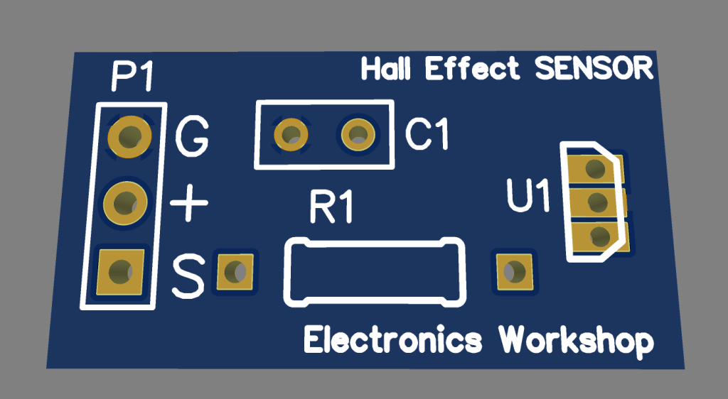
The circuit shown is a simple magnetic sensor module built around the SS411A Hall Effect sensor, designed to detect the presence of a magnetic field and provide a digital output. The module operates from a +5 V power supply, which is connected through the P1 header. The three pins of the header provide +5 V, Ground (GND), and the Output (OUT) signal, making it easy to interface the module with a microcontroller such as an Arduino, ESP32, or Raspberry Pi. The SS411A Hall Effect sensor (U1) continuously monitors the surrounding magnetic field. When a magnet of the correct polarity is brought close to the sensor, the internal Hall element detects the magnetic flux and changes the state of the output pin, producing a digital signal that can be used to trigger LEDs, relays, alarms, or other electronic circuits.
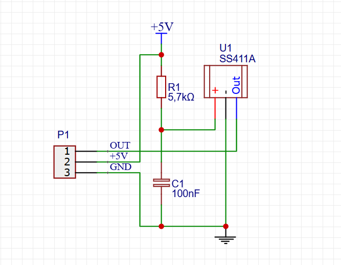
To ensure stable and reliable operation, the circuit includes a 5.7 kΩ pull-up resistor (R1) connected between the +5 V supply and the sensor’s output. This resistor keeps the output in a logic HIGH state when no magnetic field is detected. When the sensor is activated by a magnet, it pulls the output LOW, creating a clear digital switching signal. A 100 nF ceramic capacitor (C1) is connected across the power supply rails to act as a decoupling capacitor, filtering electrical noise and minimizing voltage fluctuations that could otherwise cause false triggering. Together, the SS411A sensor, pull-up resistor, and decoupling capacitor form a simple, compact, and reliable magnetic sensing circuit suitable for applications such as door and window security systems, position sensing, speed detection, industrial automation, and DIY electronics projects.
PCB files
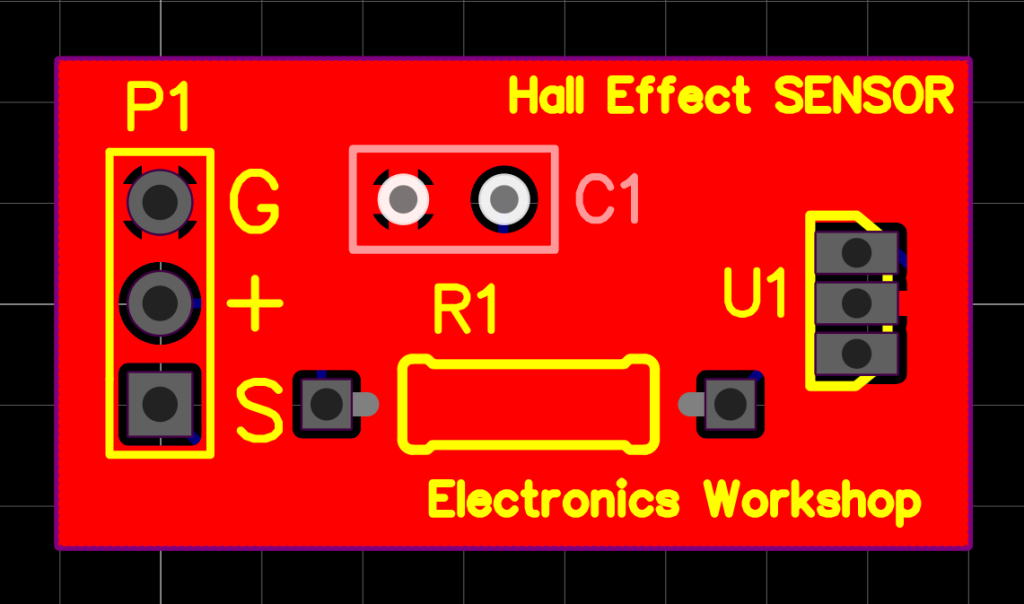
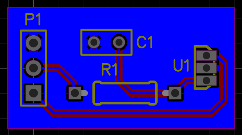
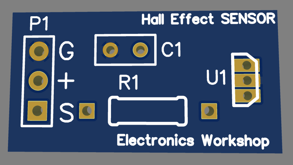
3d Files
Manufacturing Files
Bill of Materials
Pick and Place
Order Directly from PCB WAY
I have already uploaded all these required manufacturing files in PCBWAY website. You can easily go to the below link and place you order, and get your Own Home Automation PCB manufactured from one of the best pcb manufacturer PCBWAY
Conclusion
Designing a magnetic sensor using the S411A Hall Effect sensor is an excellent way to explore contactless sensing technology. With only a few components, this project delivers reliable magnetic field detection suitable for a wide range of applications, from security systems and robotics to automation and industrial controls. Its simple design, low power consumption, and ease of integration make it an ideal project for beginners as well as experienced electronics enthusiasts looking for a dependable magnetic sensing solution.
Numerical Calculator
Best free online calculators for engineers, students and everyday life — from Ohm’s Law, LED resistors and RLC resonance to BMI, calories, pregnancy due dates and EV savings — each with live diagrams and step-by-step math.
Numerical calculator : https://numericalcalculator.com/
Frequently Asked Questions (FAQs)
1. What is the S411A Hall Effect sensor used for?
The S411A is used to detect the presence of a magnetic field and provide a digital output for applications such as door sensors, speed measurement, position detection, and automation systems.
2. What voltage does the S411A operate on?
The sensor typically operates from 3.3V to 5V DC, with 5V being the most commonly used supply voltage.
3. Can I connect the S411A directly to an Arduino?
Yes. The digital output of the S411A can be connected directly to a digital input pin on an Arduino, ESP32, Raspberry Pi Pico, or other microcontrollers.
4. Why doesn’t the sensor respond to my magnet?
The S411A is polarity-sensitive, meaning it detects only a specific magnetic pole. If there is no response, reverse the magnet or use a stronger magnet.
5. What are the main advantages of using a Hall Effect sensor over a mechanical switch?
Hall Effect sensors offer contactless operation, faster response times, no mechanical wear, greater reliability, and a longer operational life compared to traditional mechanical switches.