Introduction
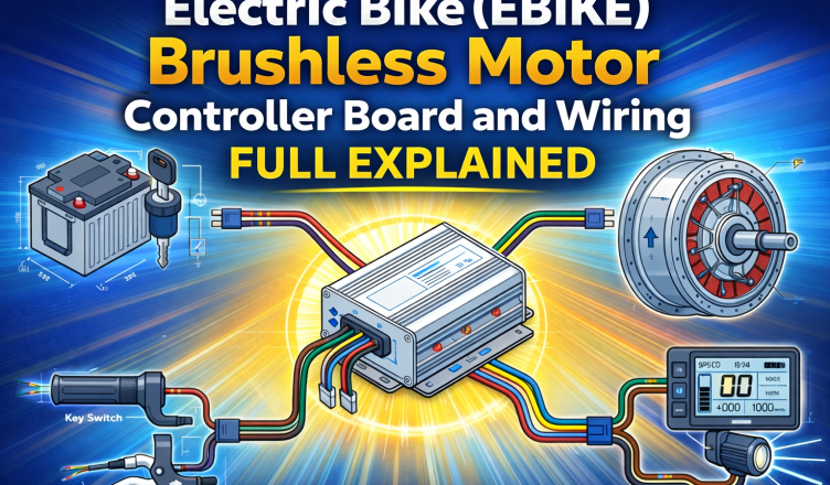
Electric bikes (EBIKES) have become one of the most efficient and eco-friendly modes of transportation. At the heart of every electric bike lies a brushless motor controller, a crucial electronic board that manages power flow, speed control, braking, and communication between different components.
Understanding the EBIKE brushless motor controller board and its wiring diagram is essential for anyone involved in electric bike building, repairing, or upgrading. In this article, we will break down the complete wiring logic, explain each section of the controller system, and help you understand how all components work together in a real-world EBIKE setup.
What Is a Brushless Motor Controller in an EBIKE?
A brushless motor controller is an electronic unit that controls the operation of a BLDC (Brushless DC) hub motor. It converts DC power from the battery into controlled three-phase signals required to drive the motor efficiently.
The controller also acts as a central hub, connecting:
- Battery and power switch
- Hub motor
- Throttle and brake sensors
- Display unit and accessories
Without the controller, smooth acceleration, speed regulation, and safe braking would not be possible.
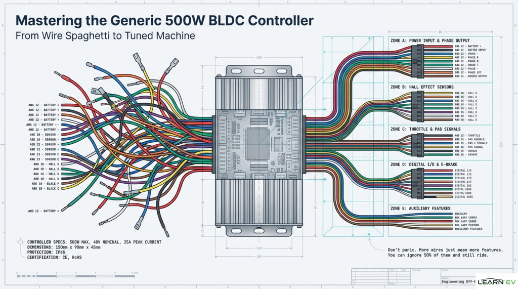
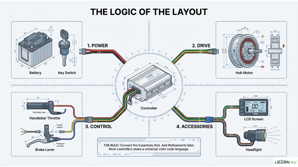
Overview of the EBIKE Controller Wiring Layout
The wiring layout of an electric bike controller is generally divided into four main sections:
- Power Section
- Drive Section
- Control Section
- Accessories Section
Each section serves a specific purpose and must be connected correctly for safe and reliable operation.
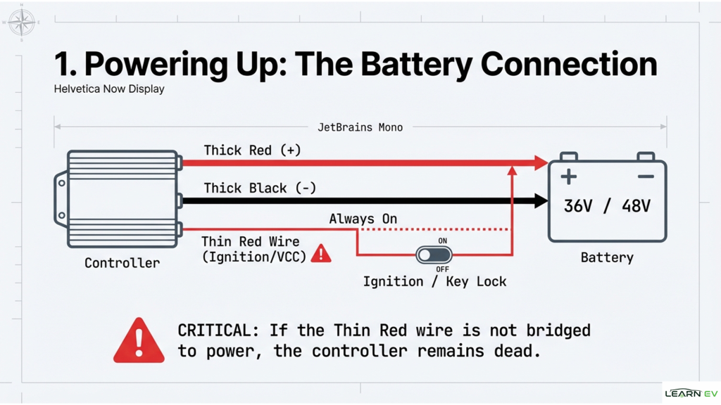
Power Section – Battery and Key Switch
The power section supplies electrical energy to the controller.
Components Involved:
- Battery pack (typically 24V, 36V, 48V, or higher)
- Key switch or power lock
- Main power cables (thick red and black wires)
Explanation:
The battery provides DC power to the controller through heavy-gauge wires. A key switch is usually connected in series to enable or disable the controller safely. When the key is turned ON, the controller becomes active and powers all internal circuits.
Important Tip:
Always ensure correct polarity while connecting the battery. Reverse polarity can permanently damage the controller.
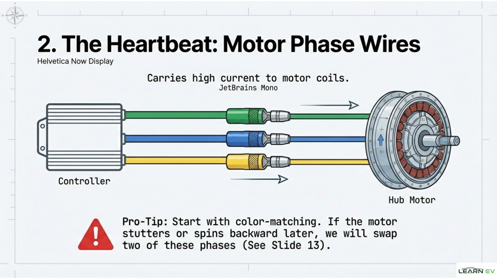
2. Drive Section – Hub Motor Connection
The drive section connects the controller to the brushless hub motor.
Components Involved:
- Three phase wires (Yellow, Blue, Green)
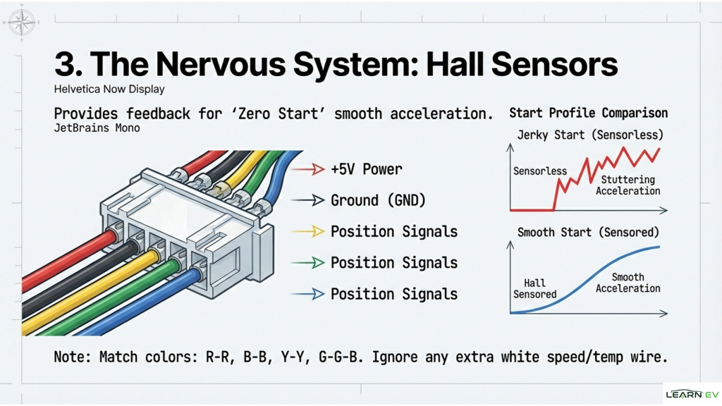
- Hall sensor connector (thin multi-wire plug)
- BLDC hub motor
Explanation:
The three thick phase wires carry high current and drive the motor. The hall sensor wires provide rotor position feedback, allowing the controller to precisely time the switching of phases.
This combination ensures:
- Smooth startup
- Better torque at low speed
- Higher efficiency
Correct matching of phase wires and hall sensors is critical for vibration-free motor operation.
3. Control Section – Throttle and Brake Inputs
The control section handles user input and safety functions.
Components Involved:
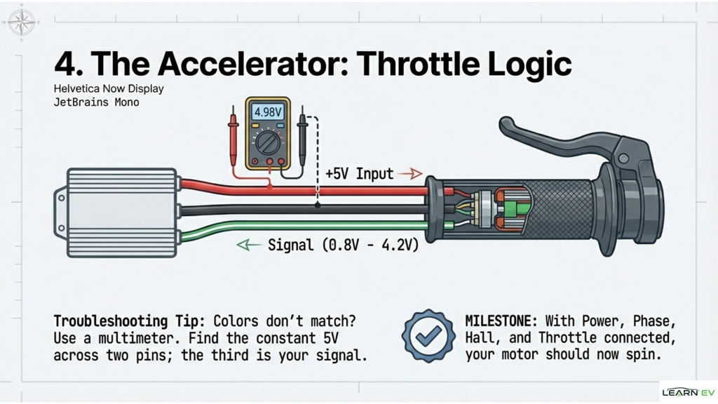
- Throttle (twist or thumb type)
- Brake levers with cutoff switches
- Control signal wires (thin wires)
Explanation:
The throttle sends a variable voltage signal (usually 1V–4.2V) to the controller, indicating how much speed or power the rider wants. The controller then adjusts motor output accordingly.
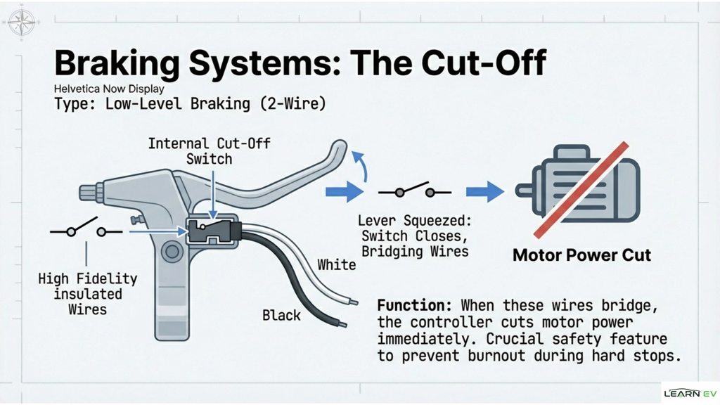
Brake levers are equipped with cutoff switches. When braking is applied:
- The controller instantly cuts motor power
- Prevents motor from fighting against braking
- Improves rider safety
This section is essential for smooth riding and accident prevention.
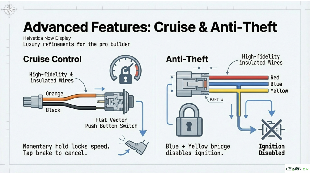
4. Accessories Section – Display, Lights, and Extra Features
The accessories section connects additional electronic features.
Components Involved:
- LCD or LED display
- Headlight or horn
- PAS (Pedal Assist Sensor)
- Communication cables
Explanation:
The display shows real-time data such as:
- Speed
- Battery voltage
- Distance traveled
- Error codes
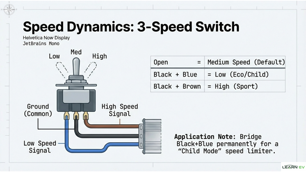
Some controllers also support programmable features like speed limits, PAS levels, and regenerative braking through the display interface.
Accessories usually operate at low voltage and are powered directly from the controller.
General Wiring Rules for EBIKE Controllers
- Connect power wires first, accessories later
- Match connector colors whenever possible
- Never connect or disconnect phase wires while powered ON
- Secure all wiring to avoid vibration damage
- Keep signal wires away from high-current cables
Most EBIKE controllers follow a universal color-coding system, which makes installation easier even across different brands
Common Mistakes to Avoid
- Reversing battery polarity
- Loose phase wire connections
- Incorrect hall sensor alignment
- Mixing different voltage components
- Ignoring waterproofing in outdoor use
Avoiding these mistakes can significantly extend controller and motor life.
Conclusion
The Electric Bike brushless motor controller board and wiring diagram form the backbone of a reliable EBIKE system. By understanding how power, drive, control, and accessories are interconnected, you can confidently build, troubleshoot, or upgrade an electric bike.
Whether you are a beginner, DIY enthusiast, or professional technician, mastering the controller wiring logic ensures better performance, safety, and long-term reliability of your electric bike.
With the right connections and proper planning, an EBIKE controller transforms simple electrical energy into smooth, efficient, and intelligent motion.