
Introduction
100BASE-TX is one of the most widely adopted Fast Ethernet standards, providing data transfer at 100 Mbps over twisted-pair cabling. It is based on the IEEE 802.3u specification and typically uses Category 5 or higher unshielded twisted pair (UTP) cables. The “TX” designation indicates transmission over two pairs of wires—one for transmitting data and the other for receiving data.
In a 100BASE-TX link, transmitting data from the host system to the physical medium involves a multi-stage process that includes encoding, scrambling, serialization, and conversion into differential signals suitable for twisted-pair transmission. Understanding the transmit data flow helps clarify how Ethernet maintains speed, integrity, and compatibility across devices.
High-Level Overview of the Transmit Path
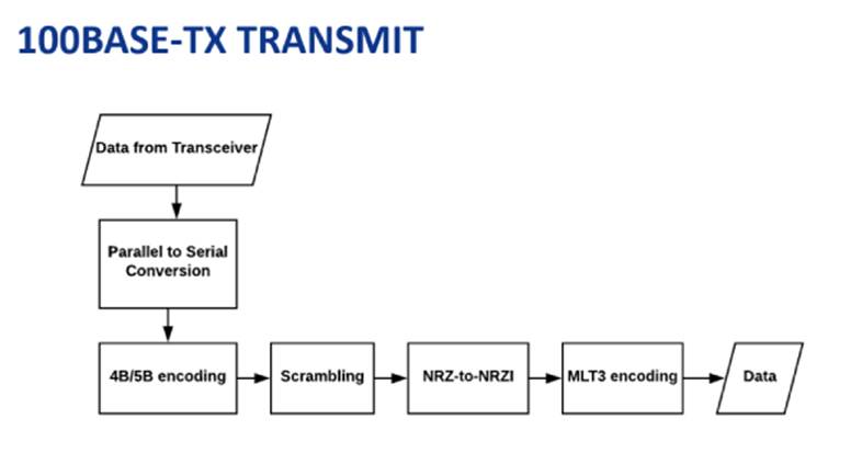
The transmit data flow in 100BASE-TX can be divided into several logical blocks:
1.Media Independent Interface (MII) Input The host system or MAC (Media Access Control) layer delivers data to the physical layer (PHY) using the MII standard interface. Data is provided as 4-bit nibbles at 25 MHz, representing 100 Mbps throughput.
2.4B/5B Encoding The PHY converts each 4-bit nibble into a 5-bit symbol using a lookup table. This ensures enough transitions for clock recovery and avoids long runs of identical bits.
3.Scrambling The 5-bit symbols are scrambled using a linear feedback shift register (LFSR) to reduce electromagnetic interference (EMI) and ensure a random distribution of ones and zeros.
4.NRZI Encoding Non-Return-to-Zero Inverted (NRZI) encoding is applied to improve signal transition characteristics. A logic “1” is represented by no transition, and a logic “0” is represented by a transition.
5.MLT-3 Encoding Finally, the data is mapped into MLT-3 (Multi-Level Transmit, 3 levels) signaling. This encoding uses three voltage levels (+, 0, -) to represent data transitions, reducing the frequency spectrum of the transmitted signal and making it suitable for twisted-pair copper cabling.
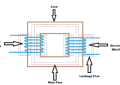
6.Transmission onto the Medium The MLT-3 signal is driven onto the twisted-pair medium via differential line drivers. Termination and impedance matching ensure signal integrity over distances up to 100 meters.
Step-by-Step Transmit Data Flow
1. Media Independent Interface (MII)
•The MII provides a standardized way for the MAC layer to communicate with the PHY.
•For 100BASE-TX, the MII operates at a 25 MHz clock, transferring 4 bits per clock cycle, which equals 100 Mbps throughput.
•The MAC sends data frames (including preamble, start-of-frame delimiter, payload, and CRC) across the MII.
•Control signals on the MII indicate frame boundaries, idle states, and error conditions.
2. 4B/5B Encoding
•Each 4-bit nibble from the MII is converted into a 5-bit codeword.
•This process ensures that the encoded stream has enough transitions for reliable clock recovery and avoids long runs of zeros or ones.
•Example mappings: 0000 (0x0) → 11110 0001 (0x1) → 01001 1111 (0xF) → 11101
•Out of the 32 possible 5-bit codes, only 16 are valid for data, while others are reserved for control symbols (Idle, Start, End, etc.).
•This results in 25% overhead, but it guarantees robust signaling.
3. Scrambling
•After 4B/5B encoding, the data stream undergoes scrambling.
•A scrambling polynomial, often based on a 11-bit linear feedback shift register, ensures pseudo-randomization of the bit sequence.
•Purpose: Minimize electromagnetic interference by avoiding repetitive patterns. Prevent spectral peaks that can interfere with other systems. Maintain DC balance in the signal.
•Importantly, scrambling is self-synchronizing, so the receiver can descramble without requiring a separate synchronization signal.
4. NRZI Encoding
•The scrambled bitstream is then encoded using NRZI (Non-Return-to-Zero Inverted).
•Rule: Logical 0 = Transition Logical 1 = No transition
•NRZI improves transition density, further assisting in clock recovery.
•However, NRZI alone does not guarantee sufficient transition density, which is why 4B/5B encoding is still necessary.
5. MLT-3 Encoding
•The NRZI signal is then mapped into MLT-3 (Multi-Level Transmit – 3 levels) encoding.
•MLT-3 uses three voltage levels: +, 0, and −.
•Rule: A logic 1 causes the signal to move to the next state in the sequence (+ → 0 → − → 0 → + …). A logic 0 means the signal stays in the same state.
•Benefits of MLT-3: Reduces the maximum fundamental frequency to 31.25 MHz (instead of 125 MHz). Makes it easier to transmit over twisted-pair cabling without excessive crosstalk or attenuation.
•Example: Input bitstream: 11001 NRZI output: No transition, No transition, Transition, No transition, Transition MLT-3 signal levels: 0, +1, 0, -1, 0
6. Line Drivers and Transmission
•After MLT-3 encoding, the signal is passed to the line driver stage.
•The line driver provides sufficient current to transmit the differential signals over the twisted-pair cable.
•Impedance matching (typically 100 Ω) is crucial to avoid reflections.
•The result is a balanced, differential signal that travels across the cable to the receiver.
Example of Data Flow in Practice
Let’s walk through a small sequence:
1.Input nibble from MII: 0101 (hex 5)
2.4B/5B encoding: 0101 → 10101
3.Scrambling: Suppose the scrambler outputs 11010
4.NRZI encoding: Start at logic high. 1 → No transition (remain high) 1 → No transition (stay high) 0 → Transition (go low) 1 → No transition (stay low) 0 → Transition (go high)
5.MLT-3 mapping: Sequence generates voltage states such as 0 → +1 → +1 → 0 → -1 → 0.
6.Line driver output: Differential voltages representing MLT-3 signals appear on the cable.
The receiver will invert this process: detect MLT-3 levels, recover the NRZI sequence, descramble, map back from 5B to 4B, and finally deliver the data to the MAC layer.
Advantages of This Data Flow
•Robust clock recovery: 4B/5B and NRZI ensure transition density.
•Noise reduction: Scrambling spreads energy across the spectrum.
•Cable efficiency: MLT-3 lowers bandwidth requirements.
•Compatibility: Works with existing twisted-pair infrastructure.
Challenges in Transmit Path
While effective, the transmit data flow of 100BASE-TX faces several challenges:
•Signal attenuation over 100 meters requires careful cable quality.
•Crosstalk between twisted pairs can distort MLT-3 signals.
•Jitter accumulation can complicate clock recovery at the receiver.
•Encoding overhead (4B/5B adds 25% redundancy) slightly reduces efficiency.
However, these challenges are mitigated through robust PHY design and compliance with Ethernet cabling standards.
Conclusion
The 100BASE-TX transmit data flow is a carefully engineered pipeline that transforms raw nibbles from the MAC layer into robust, noise-resistant, and cable-friendly differential signals. Through 4B/5B encoding, scrambling, NRZI, and MLT-3 encoding, the system ensures reliable 100 Mbps communication over twisted-pair copper.
Each stage plays a vital role:
•MII ensures interoperability between MAC and PHY.
•4B/5B encoding guarantees transition density.
•Scrambling reduces EMI.
•NRZI encoding aids clock recovery.
•MLT-3 signaling makes high-speed data feasible over inexpensive cables.
This transmit data flow highlights the balance between theoretical data representation and practical physical layer transmission, which is the cornerstone of Ethernet technology’s success.
Related Articles
Efficient Logic and Memory Implementation with FLEX 10K EABs