
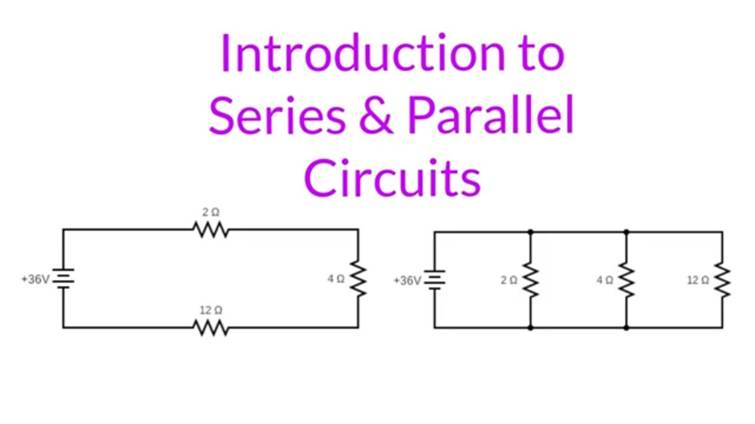
Introduction
Electric circuits are fundamental to the operation of virtually all electronic devices. Understanding the basics of series and parallel circuits is essential for anyone working with electronics, from hobbyists to professional engineers. This guide will provide a comprehensive overview of series and parallel circuits, including their characteristics, applications, advantages, and disadvantages.
Series Circuits
Definition
A series circuit is a type of electrical circuit in which components are connected end-to-end to form a single path for electric current to flow. In a series circuit, the same current flows through each component without any branching off.
Key Characteristics
•Single Current Path: All components share the same current.
•Voltage Division: The total voltage of the source is divided among the components based on their resistance.
•Current Continuity: The current is the same through every component, indicating that if one component fails, the entire circuit stops functioning.
Example
A common example of a series circuit is a string of Christmas lights. If one bulb burns out, the entire string goes dark because the electrical path is interrupted.
Components in Series
•Rtotal=R1+R2+⋯+Rn
•Ctotal1=C11+C21+⋯+Cn1
•Inductors: When inductors are connected in series, the total inductance is the sum of the individual inductances, much like resistors. This sum enhances the circuit’s ability to resist changes in current flow, which is critical in applications like filters and tuning circuits.
Parallel Circuits
Definition
A parallel circuit is defined by its unique characteristic of having components connected across the same two points, creating multiple paths for current to flow. This setup allows each branch to operate independently from the others, which is crucial in systems where consistent voltage across components is necessary.
Key Characteristics
•Multiple Current Paths: Current divides among the various branches according to the resistance of each branch.
•Uniform Voltage: All components share the same voltage, which is equal to the voltage of the source.
•Independent Operation: The failure of one component does not stop the flow of current in other paths.
Example
A common example of a parallel circuit is in home lighting systems. If one light bulb goes out, the others continue to work because each bulb is independently connected to the power source.
Components in Parallel
•Rtotal1=R11+R21+⋯+Rn1
•Ctotal=C1+C2+⋯+Cn
•Ltotal1=L11+L21+⋯+Ln1
Series vs. Parallel Circuits: Key Differences
Comparison Table
TableCopy
| Feature | Series Circuit | Parallel Circuit |
| Voltage Distribution | Voltage is divided among components, proportional to each component’s resistance | Voltage across each component is the same and equals the source voltage |
| Current Flow | The same current flows through each component. If one fails, the circuit stops | Current divides among branches based on resistance. One failure does not stop others |
| Resistance | Total resistance is the sum of all resistances: Rtotal=R1+R2+⋯+Rn | Total resistance decreases with more branches: Rtotal1=R11+R21+⋯+Rn1 |
| Component Dependency | Components depend on each other; failure of one affects the whole circuit | Components operate independently; failure of one doesn’t impact others |
Implications for Circuit Design
•Voltage Requirements: In series circuits, careful calculation must ensure each component receives the correct voltage. In parallel circuits, designers can ensure all components receive the same voltage, which is simpler for devices with uniform voltage needs.
•Safety and Reliability: Parallel circuits are generally more reliable for consumer electronics because a single component failure does not compromise the entire circuit.
•Current and Resistance Management: Designers must consider the total resistance and current handling capacity. Series circuits are suitable where high resistance is beneficial, while parallel circuits are advantageous in applications requiring lower overall resistance.
Advantages and Disadvantages
Series Circuits
•AdvantagesSimplicity in Design: Series circuits are straightforward to design and require fewer connections and components.Voltage Control: They allow for precise voltage distribution across components, which is useful in applications requiring different voltage levels.
•DisadvantagesReliability Issues: If one component fails, the entire circuit fails, which can be a major drawback in critical systems.Current Limitation: The same current flows through all components, which can limit the functionality in diverse load conditions.
Parallel Circuits
•AdvantagesIncreased Reliability: If one component fails, the rest of the circuit continues to operate, enhancing the overall reliability.Flexible Current Distribution: Each branch can carry a different current, making it suitable for circuits that power multiple devices or components.
•DisadvantagesComplexity in Design: Parallel circuits can be more complex to design due to the need for more connections and careful calculation of load distribution.Voltage Stability Required: All components share the same voltage, which requires stable and consistent voltage supply to prevent performance issues.
Troubleshooting and Safety in Series and Parallel Circuits
Safety Precautions
•Always Disconnect Power Before Servicing: Prevent electrical shock and other hazards.
•Use Insulated Tools and Wear Protective Equipment: This reduces the risk of accidental short circuits and personal injury.
•Verify with Reliable Instruments: Use well-calibrated multimeters and oscilloscopes to ensure accurate readings and diagnosis.
Common Issues and Solutions
TableCopy
| Issue | Series Circuit | Parallel Circuit |
| Complete Power Failure | Check each component for continuity; replace any failed elements | Check each branch; the issue might be localized |
| Inconsistent Voltage | Verify the total voltage distribution across components | Ensure all connections are secure and contacts are clean |
| Overheating Components | Check for undersized components that may be overloaded | Verify if current distribution is as expected, adjust loads |
| Intermittent Operation | Inspect for loose connections or damaged wires | Look for loose connections or fluctuating supply voltage |
Conclusion
Understanding the differences between series and parallel circuits is crucial for designing efficient and reliable electronic systems. Series circuits are simpler and allow for precise voltage control but are less reliable due to their dependence on each component. Parallel circuits offer increased reliability and flexible current distribution but are more complex to design and require stable voltage supply. By mastering these concepts, engineers and hobbyists can make informed decisions to optimize their circuit designs for specific applications.